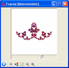
A line fractal is obtained by dividing a horizontal or vertical line into a number of individual segments that are then translated as desired while still keeping the segments connected. That design is then used as a generator. The fractal is obtained by iteratively replacing each segment with a scaled copy of the generator. This is an example of an L-system or turtle type fractal. You can choose the number of segments from 2 to 15, then use the mouse to rearrange the points.
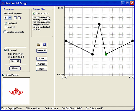
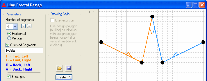
If you check the box for "Oriented Segments", you have the option to specify each of the individual segments as being oriented in the forward or backward direction, with the generator placed either to the left or right relative to the direction of the segment. At each iteration the segments are replaced with a scaled copy of the generator such that the copy appears to the appropriate side of the oriented segment it is replacing. Recursion cannot be used with oriented segments.
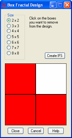
A box fractal is obtained by dividing a square box into equal subsquares, then removing the subsquares that should not be part of the design. Each remaining subsquare corresponds to a transformation in the IFS. Each transformation will consist of a scaling and translation.
This menu item will display a dialog box in which you can
choose to use a 2x2 up to 10x10 grid. Click on a subsquare to
remove it (the color will change to white.) Click again if you want to
put the subsquare back into the design (the color will change back to
red.) After you have chosen which squares to remove, click on the
"Create IFS" button.
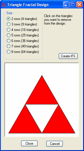
A triangle fractal is obtained by dividing an equilateral triangle into equal subtriangles, then removing the subtriangles that should not be part of the design. Each remaing subtriangle corresponds to a transformation in the IFS. Each transformation will consist of a scaling and translation, and possibly a rotation by 180° For example, in the case where the original equilateral triangle is divided into 4 subtriangles, the center triangle has to go in upside down.
This menu item will display a dialog box in which you can choose to
divide the equilateral triangle into from 2 to 10 rows, corresponding
to 4, 9, 16, 25, 36, 49, 64, 81, or 100 subtriangles, respectively. Click on a subtriangle
to remove it (the color will change to white.) Click again if you want
to put the subtriangle back into the design (the color will change back
to red.) After you have chosen which triangles to remove, click on the
"Create IFS" button.
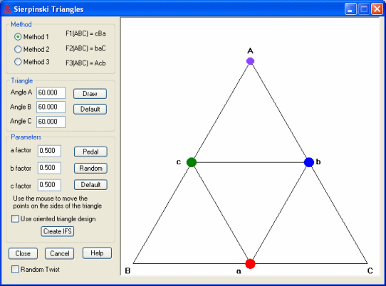
Rather than constructing the Sierpinski triangle by removing interior triangles, you can view the construction as transforming the large triangle ABC into each of three smaller triangles by mapping each vertex of ABC to a vertex of the smaller triangle. Method 1 is the same as removing the interior triangle since the orientation of the vertices is not changed. The other two methods change the orientation of the vertices. See the individual help file for more details (the help file is also available from the dialog box).
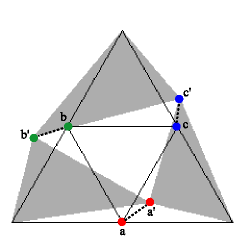
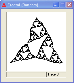
Check the "Random Twist" box to create a twisted Sierpinski triangle. This construction starts out exactly like describe above. At each iteration, however, each of the points a, b, and c is moved a small amount in a random direction to the points a', b', and c' (see figure on the left). The example on the right shows a twisted Sierpinski triangle after 5 iterations. The image is no longer a strict self-similar fractal because of the random variations.
You can adjust the amount of twisting using the slider. There are 10 positions from no twist to large twisting. The Page Up and Page Down keys will move the slider among the four basic choices while the left and right arrow keys will move it in smaller increments. The image can be drawn in one color or drawn using the three IFS colors. You can also choose whether to fill each triangle as it is drawn or just draw the sides. The up and down arrow keys can be used to increase or decrease the iteration count. You can specify a specific iteration by typing ctrl-n for n from 1 to 8. Clicking on the Draw button will also create the underlying IFS code without the random twists in the IFS window. The ctrl-A, ctrl-F, and ctrl-G keyboard shortcuts will toggle the axes, fixed points, and grid, respectively, in the fractal window.

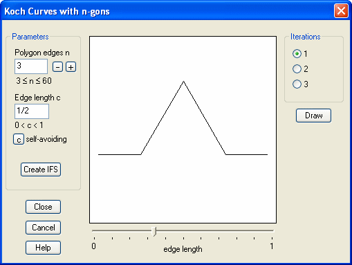
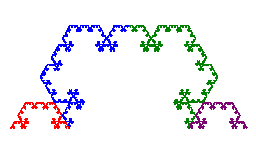
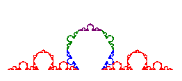
This process can be generalized by choosing two parameters: a number c with 0 < c < 1 that defines the length of the removed subinterval, and an integer n ≥ 3 that defines a regular n-gon which replaces the removed segment. This produces the (n, c)-Koch curve. The dialog box allows you to specify the values of c and n. You can adjust the value of n up or down using the buttons labeled with the plus and minor signs. You can adjust the value of c using the slider. Select a radio button to preview the first, second, or third iteration for the Koch curve for the current values of c and n. See the individual help file for more details (the help file is also available from the dialog box).
|
|
| (3, 1/2)-Koch curve | (6, 0.14)-Koch curve |
The (n, c)-Koch curve is self-avoiding if the curve does not cross itself. Click on the "self-avoiding" button to compute the value for which the Koch curve will be self-avoiding for all c less than that value.
For further information, see the paper "The Trouble with von Koch Curves Built from n-gons," by Tamás Keleti and Elliot Paquette in the American Mathematical Monthly, Vol. 117, No. 2 (February 2010), 124-137. An online supplement containing an interactive Java applet is available at the MAA periodicals website.
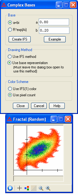 Let z be a
complex number with |z| < 1. We can use z as the base of a
number system with digits 0 and 1. The set of numbers that can be
written in this base with digits 0 and 1 is given by {Σ zn
: n in A, A a subset of the positive integers}. Choose this option to
draw this set.
You can give the value of z in the form a+bi or in the form ReAi. Click on "Create IFS" to define the two functions that form the IFS: f1(w) = zw, f2(w) = zw + z.
The image associated with this IFS can be drawn two ways. One is to use the regular IFS methods (random or deterministic). The other is to use the idea of the base representation to compute and plot points of the form Σ zn for n in A, where A is a subset of the integers {1, 2, ..., 22}. If you want to use this method to draw the image, you must have this dialog box open when you do the drawing.
If the IFS drawing method is chosen, the colors used will be those set in the IFS window. If the base representation method is chosen, the image can be drawn in a solid color (as specified by the first function in the IFS). Alternatively, you can choose to color pixels according to the number of times each is plotted as one of the finite sums. The coloring is based on the gradient range and pixel count specified in the Gradient Color Options dialog (available under the Code/IFS Color Scheme menu).
For further information, see the paper "Number
Systems With a Complex Base: A Fractal Tool for Teaching Topology,"
Daniel Goffinet, American Mathematical Monthly,
Vol. 98, No. 3 (March 1991), 249-255.
The integer matrix M should be chosen so that the eigenvalues have modulus greater than 1. The columns vectors of M form a parallelogram with area given by m=|det(M)|. The span of these vectors will partition the plane into parallelograms each containing m lattice points with integer coefficients inside the parallelogram or on two of the edges. Click the button "Draw Lattice" to draw these parallelogram. Use the Page Up and Page Down keys to zoom in and zoom out, respectively. Use the arrow keys to shift the window. The Home key will return you to the default view.
The set of all lattice points in the plane form a complete residue system for M consisting of m equivalence classes. Two lattice points are equivalent if they occur in equivalent positions in different parallelograms. You can click on the lattice points shown to choose one point from each equivalence class (or to deselect that point.) These points will be shown in red. You cannot select more than one point from each equivalence class.
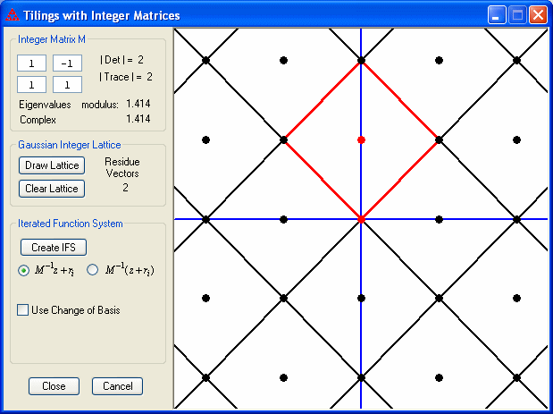
After you have chosen the lattice points (also referred to as residue vectors), create the IFS by clicking the button. There are two choices for how the IFS is created based on how the residue vectors are used in determining the translation for each function in the IFS.
It is also possible to use a change of basis matrix to modify the transformations to produce tiles with radial symmetry.
For more details, see the papers
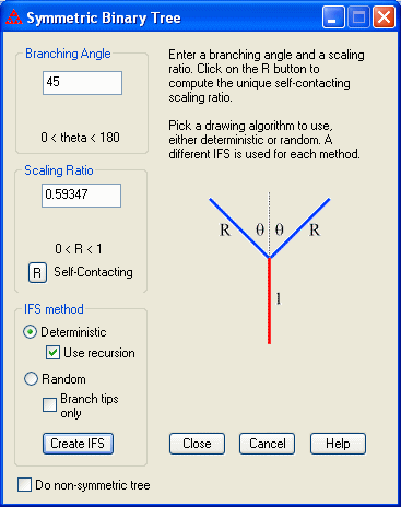
A symmetric binary tree T(r,θ) is defined by two parameters, the scaling ratio r (a real number between 0 and 1) and the branching angle θ (an angle between 0° and 180°). The trunk splits into two branches, one on the left and one on the right. Both branches have length equal to r times the length of the trunk and form an angle of θ with the trunk. Each branch then divides by the same rule.
A self-contacting symmetric binary tree has self-intersection but no actual branch crossings. Click on the R button to have the program compute the unique scaling ratio that gives a self-contacting binary tree.
By checking the box for "Do non-symmetric tree" it is possible to choose different angles and scaling ratios for the left and right branches.
For more information, see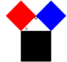
A Pythagorean tree fractal is constructed from three squares. It is named after Pythagoras because the three squares enclose a right triangle and thus the sides of the squares satisfy the Pythagorean Theorem. The design is determined by choosing the angle θ between the red and black squares. The construction begins with the black square. Attach a right triangle to the "top" side of the square along the right triangle's hypotenuse. Attach two squares (the red and blue ones in the figure) along the other two sides of the triangle. The angle between the red square and the black square is set in advance. The same procedure is then applied to each of the smaller squares with the right triangle always attached in the same orientation.
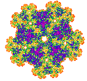 Symmetric fractals are created using
either the cyclic group Zn of order n or the dihedral group Dn of order 2n. These are both symmetry groups. The group Zn consists of counterclockwise rotations through angles that are multiples of 360°/n. The group Dn consists of symmetries of a regular polygon with n sides, including both the same rotations as Zn and also reflections. To design a symmetric fractal you start by either defining a contractive affine transformation to use as the base or selecting an IFS from the list in the Fractals menu.
In the first case, suppose f is the affine transformation. Let G be either a cyclic group or a dihedral group. Let gk be the elements of the group G for k from 1 to order(G), the order of the group (either n or 2n). Then we take as the iterated function system the set of functions {gkf : k = 1 to order(G)}, where gkf is the composition of the symmetry gk with the transformation f. The attractor for this IFS will have the symmetry corresponding to the group G. If instead you select an IFS in the Fractals menu to use in the construction, then the new IFS is obtained by applying the symmetry group multiplication just described to each of the functions in the selected IFS.
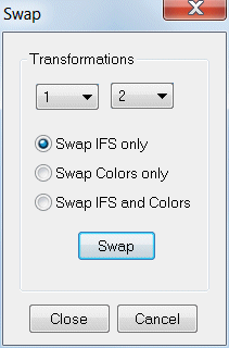
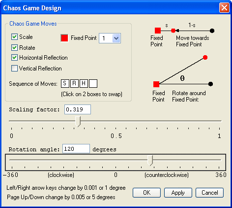
In the Chaos Game mode, creates an exact duplicate of the moves for the selected fixed point (including the location of the fixed point.)
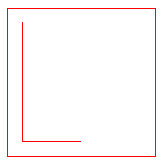
Other choices are an oriented equilateral triangle (containing an "L"), a unit line or a regular polygon with the number of sides from 3 (equilateral triangle) to 9 (nonagon).
You may also load an initial polygon from a text file with extension ".gon". The file should consist of a list of coordinates, one pair of coordinates to a line. If the polygon is to end at the same point where it started, that point should be listed twice, once at the beginning and once at the end.
A third option is to design you own initial polygon. Click in the Design window at the location of the first point. Each subsequent click of the mouse will plot a new vertex of the polygon. The cursor will change to a crosshair when the mouse is close to the initial vertex. A click in that case will use the initial vertex. Press "D" to delete the last vertex drawn. Pressing "L" while you are drawing the polygon allows you to "lift" the pen so that you can start a new polygon. Press "Q" after you have chosen the last vertex. You can also double click the mouse when you are done. If you show the grid while designing the polygon (ctrl-G), then holding down the shift key while clicking will snap the vertex to the nearest corner on the grid. Use the plus and minus keys to rotate among the four grid sizes (0.05, 0.1, 0.125, 0.25). If you have created a grid with unequal scale along the x and y axes, then pressing the plus or minus key will convert back to a square grid. The plus key will use the larger grid value while the minus key will use the smaller grid value.
If the initial polygon consists of disconnected parts because the pen was "lifted" during the construction, and the polygon is saved to a file, then a point with coordinates (1000,1000) will be written to the file to separate the vertex where one polygonal piece ends from the first vertex of the next piece.
Use this to display a preview window that shows a rough approximation to the limit fractal for the IFS. The default number of points to plot is 2000 (as displayed at the bottom of the window). You can increase or decrease the amount by 500 points using the plus and minus keys on the keyboard or number pad. = But this preview image is "live". As you modify the design with the mouse, using keyboard shortcuts, or choosing from the design menu, the preview window will automatically update. You can then use the fractal window to draw a more detailed image of the resulting IFS. On an older and slow computer, there may be some delay observed as the new points are recomputed -- in that case you might not want to use the preview window, or try decreasing the number of points plotted. Pressing ctrl-W will adjust the fractal window to an appropriate scale, and use the same scale for the preview window. You can do this while you are moving the mouse in editing the design if the preview image starts to extend too far outside the preview window.
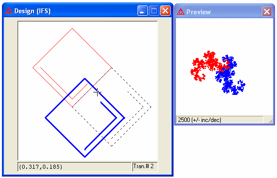
If the preview window is visible, it will preview the image for any new IFS chosen from the Fractal menu. This can be a quick way to see what each fractal in the menu would like before making a more detailed plot in the Fractal window.
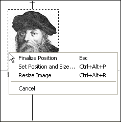 You can load a picture into the Design window from a file or pasted from the clipboard. The picture
may be of bitmap, GIF, or JPEG format. When you first load an image the image will appear with dashed lines around the edges. While the dashed lines are present, you can move the image around the design window to a desired location. You can display the axes or the grid to help guide your placement by pressing ctrl-A or ctrl-G, respectively. If you right click on the image while the dashed lines are present, a popup menu will appear that allows you to bring up a dialog box to set the precise location of the image (based on one of the four corners) as well as change the width and height. Or you can choose to resize the image manually. In this case, grab handles will appear in the corners and along each edge which you can use to resize the image. Once the image is where you want it, press the escape key, click anywhere outside the image, or choose Finalize Position from the popup menu to set the image's location and erase the dashed lines around the edges. You can reselect the image by pressing the escape key. This allows you to move or resize the image. Press the escape key again or click outside the image to deselect the image.
Choose Clear Picture to clear
the picture from the Design Window.